
CFM Full Form: What CFM Means in Air Compressors and How to Calculate It
The CFM full form is cubic feet per minute. It is the unit most compressor makers, dryer suppliers and maintenance teams in India use to describe how much air a compressor delivers or a machine consumes. If your compressor nameplate says 500 CFM, it claims to deliver 500 cubic feet of air every minute. This article explains what CFM really means, why one number can mean three different things, and how to work out the CFM your plant actually gets.

What Is CFM?
CFM measures volumetric flow: the volume of air that passes a point in one minute. One cubic foot is about 28.3 litres, so 1 CFM is roughly 0.0283 m³/min, or about 1.7 m³/h.
Indian plants often mix units. A compressor quotation may be in CFM, a dryer in m³/min, and a flow meter display in Nm³/h. Our compressed air flow unit converter switches between CFM, m³/min, m³/h, Nm³/h and l/s in one step, so you can compare like with like before you size a dryer or approve a new compressor.
Useful conversions to keep at hand:
- 1 CFM ≈ 0.0283 m³/min ≈ 1.70 m³/h ≈ 0.472 l/s
- 1 m³/min ≈ 35.3 CFM
- 100 m³/h ≈ 58.9 CFM
CFM, SCFM, ACFM and FAD: Why the Same Number Can Mean Different Things
Air is compressible. A cubic foot of air at 7 bar holds far more air than a cubic foot at atmospheric pressure, and warm air takes more space than cold air. So a CFM figure is only meaningful when you know the conditions it refers to.
- ACFM (actual CFM) is volume at the real pressure and temperature at the point of measurement. It changes whenever pressure or temperature changes.
- SCFM (standard CFM) is volume corrected to a fixed reference pressure and temperature. Because the reference is fixed, SCFM tells you how much air (by mass) is moving, whatever the line conditions.
- Nm³/h (normal cubic metres per hour) is the metric equivalent of SCFM, usually referenced to 0 °C and 1.013 bar.
- FAD (free air delivery) is the figure compressor makers publish. It is the air the compressor delivers, converted back to the conditions at its inlet, and is tested to ISO 1217.
The practical point: when you compare a compressor’s rated CFM with what your plant consumes, both numbers must be on the same basis. A flow meter reading in Nm³/h and a nameplate in FAD CFM can differ by a noticeable margin on a hot afternoon, even when the compressor is perfectly healthy. Different suppliers also use different standard reference conditions, so always check which one a datasheet uses.
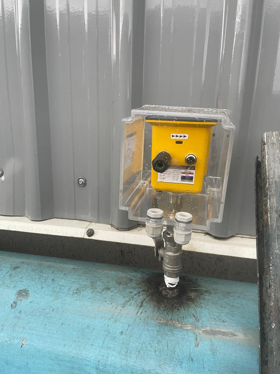
This is why thermal mass flow sensors are popular in compressed air: they measure mass flow directly and report it in standard units, with no separate pressure and temperature correction. Our insertion thermal mass flow sensor fits into an existing pipe through a ball valve, and the inline thermal mass flow sensor suits smaller lines and machine-level measurement.
How to Calculate the CFM of an Air Compressor
The nameplate tells you what the compressor delivered when it was new, under test conditions. Wear on the airend, a choked inlet filter or a slipping belt can reduce real delivery without any alarm. There are two practical ways to check it.
Method 1: The receiver pump-up test
This test uses an air receiver of known volume and a stopwatch. Isolate the receiver from the plant, run the compressor, and time how long it takes to raise the pressure between two points.
FAD (m³/min) = V × (P2 − P1) ÷ P0 ÷ t
- V = receiver volume plus the pipework volume up to the isolation valve, in m³
- P1, P2 = start and end pressure, in bar (gauge)
- P0 = atmospheric pressure, about 1.013 bar
- t = time taken, in minutes
Worked example: a 2 m³ receiver rises from 5 bar to 7 bar in 40 seconds.
FAD = 2 × (7 − 5) ÷ 1.013 ÷ 0.667 ≈ 5.9 m³/min ≈ 209 CFM.
If the nameplate says 250 CFM, this compressor is delivering about 16% less than rated. That is worth investigating. The test is approximate: air heats up as it is compressed, and pipe volume is easy to underestimate. Treat it as a quick health check, not a calibration.
Method 2: Measure it continuously with a flow sensor
A flow sensor on the compressor discharge, logging alongside a power meter, gives you real CFM under real production conditions, every minute of every shift. It also shows how delivery changes as the compressor loads and unloads, which a one-off test cannot. For large mains where a shutdown is not possible, a pitot tube flow sensor can be installed under pressure through a hot-tap fitting.
CFM to kW: How Much Power Does Each CFM Cost?
Compressed air is one of the most expensive utilities in a plant, so the most useful number is not CFM alone but specific power: kW consumed per unit of air delivered, often written as kW per 100 CFM.
Specific power = compressor input kW ÷ delivered CFM × 100
For example, a compressor drawing 45 kW and delivering 209 CFM has a specific power of about 21.5 kW per 100 CFM. Compare this with the maker’s published datasheet value at the same pressure. Many manufacturers publish these figures in CAGI-format datasheets. A rising specific power over months is an early sign of wear or poor control, long before the compressor fails.
You need both numbers measured, not assumed. Power is easy to log; flow is the number most plants never measure. That missing number is why many plants believe their compressor is efficient when it is not.
How Much CFM Does Your Plant Actually Need?
Sizing a new compressor or adding one to an existing station starts with demand, and demand is not a single number. A spinning mill, a tyre plant and a pharma unit all have demand that rises and falls across shifts, with peaks when large consumers start together and troughs during breaks and maintenance.
The reliable way to find your real demand is to log flow for at least one full production week, covering every shift and a weekend. From that log you can read four figures:
- Average demand: the CFM your base-load compressors should cover efficiently.
- Peak demand: the short-term maximum your station must meet without pressure dropping below what machines need.
- Minimum demand: often leaks plus a few continuous users. If this is high on a Sunday, leaks are the likely cause.
- Demand pattern: how quickly demand changes, which decides whether a variable speed compressor or a larger receiver will help.
With these four numbers you can match compressor sizes to real load instead of guessing, and avoid buying capacity your plant will never use. Logging flow and power together on our smart monitoring software gives you this profile without anyone collecting readings by hand.
Common CFM Mistakes in Indian Plants
- Adding up machine CFM ratings to size a compressor. Machines rarely run at full demand together. Measured consumption over a typical week is a far better basis than a sum of nameplates.
- Ignoring leaks. Leaks consume CFM 24 hours a day, including on holidays. With all machines off, if the compressor still loads, that air is going to leaks. Our compressed air leak cost calculator turns leak CFM into rupees per month.
- Comparing CFM at different pressures. A compressor rated at 7 bar will deliver less air if it is run at a higher pressure. Always compare at the same pressure.
- Using a rotameter or nameplate as “measurement”. Neither tells you what the system is doing right now.
Frequently Asked Questions
What is the CFM full form in an air compressor?
Cubic feet per minute: the volume of air the compressor delivers in one minute, normally quoted as free air delivery at inlet conditions.
How do I convert CFM to m³/h?
Multiply CFM by 1.699. For example, 300 CFM ≈ 510 m³/h. Use the flow unit converter for other units.
Is higher CFM always better?
No. The right compressor delivers the CFM your plant needs at the lowest kW per CFM. Oversized compressors spend more time unloaded, still drawing power while delivering no air.
What is the difference between CFM and SCFM?
CFM (or ACFM) is volume at actual line conditions. SCFM is volume corrected to standard pressure and temperature, so it reflects the true amount of air moving.
Know Your Real CFM
CFM is simple to define and easy to misread. The plants that control compressed air costs best are the ones that measure delivered CFM and kW together, continuously, instead of trusting the nameplate. WiseAir flow sensors, power meters and smart monitoring software give you both numbers on one dashboard. Talk to our team about measuring the real CFM of your compressors.