
WAFS 109 – Explosion-Proof Thermal Mass Flow Sensor
WAFS 109 – Explosion-Proof Thermal Mass Flow Sensor
Explosion-Proof Thermal Mass Flow Meter for Compressed Air and Gases in Hazardous Areas
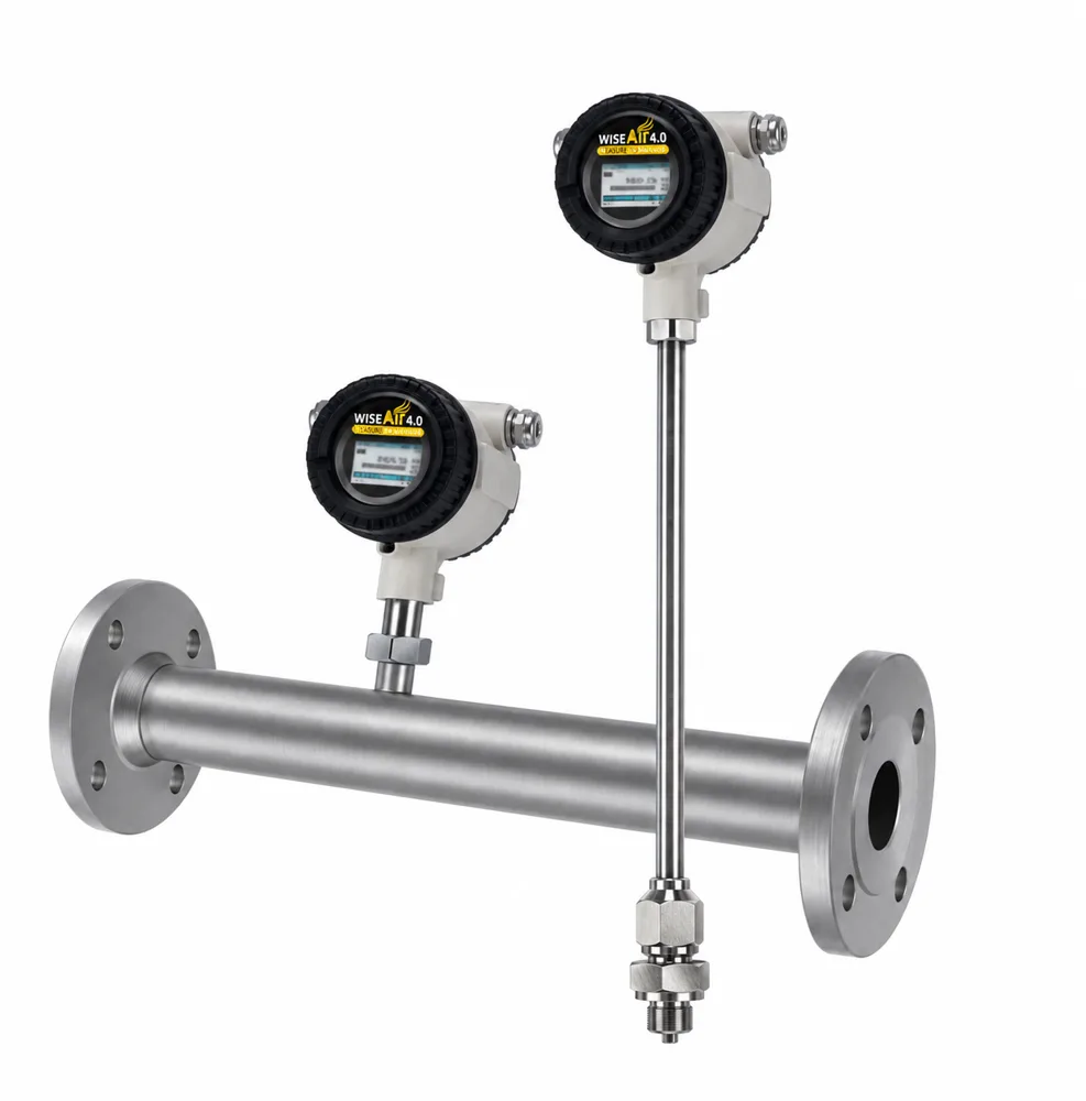
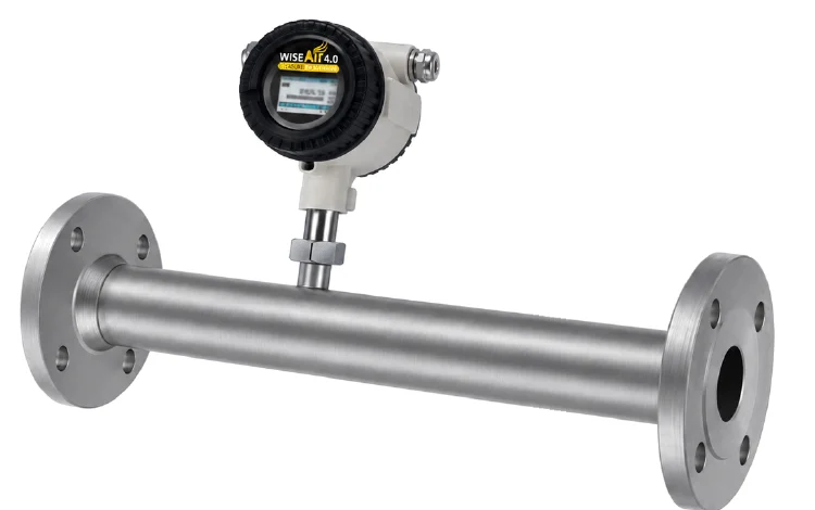
The WAFS 109 is an explosion-proof thermal mass flow sensor for compressed air, nitrogen, oxygen, carbon dioxide and other non-condensing gases in hazardous areas. It carries the explosion protection marking Ex db IIC T6 Gb / Ex tb IIIC T80°C Db with an IP67 enclosure, so it can be used where flammable gas or combustible dust may be present, such as chemical, petrochemical, pharmaceutical and power plants.
Like the other WiseAir thermal mass flow sensors, it measures mass flow directly, so no separate pressure or temperature compensation is needed. It comes in two versions: the WAFS 109 insertion type for pipes from DN20 to DN1000, installed through a 1/2″ ball valve while the line stays under pressure, and the WAFS 109-IL in-line type with its own measuring section for DN15 to DN80.
Where is the WAFS 109 used?
- Compressed air and gas consumption measurement in hazardous areas.
- Gas consumption of a single machine or a whole plant.
- Highly fluctuating flows and low-flow bypass lines, thanks to the 1:2500 turndown ratio.
- Process gas measurement, such as nitrogen, oxygen and carbon dioxide.
- Industrial processes in chemical, petrochemical and power engineering plants.
Where the area is not classified as hazardous, the WAFS 104 or WAFS 106 insertion sensors and the WAFS 105 or WAFS 107 in-line sensors are the usual choice.
What does the explosion-proof marking mean?
Ex db IIC T6 Gb means the electronics sit in a flameproof enclosure (db) approved for gas group IIC, the most demanding group, which includes hydrogen and acetylene, with temperature class T6 (surface temperature no higher than 85 °C) and equipment protection level Gb, which corresponds to Zone 1 and Zone 2 gas areas. Ex tb IIIC T80°C Db covers combustible dust: protection by enclosure (tb), dust group IIIC (conductive dust), a maximum surface temperature of 80 °C and protection level Db for Zone 21 and Zone 22 dust areas. Your site’s hazardous-area classification decides which marking you need; send us the area classification and we will confirm the documents available for your approval process.
Key features
- Thermal mass flow measurement: no pressure or temperature compensation needed, with integrated temperature measurement.
- Ultra-wide 1:2500 turndown ratio, measuring from 0.1 Nm/s to 250 Nm/s.
- Full-digital signal processing that eliminates zero-point drift for better accuracy and long-term stability.
- Intelligent diagnosis that detects sensor contamination online and protects the sensor from overheating.
- No moving parts, vibration proof and almost zero pressure drop.
- 2.0″ capacitive touch IPS LCD with a wide viewing angle for online values and sensor setting.
- Bluetooth for wireless sensor configuration and data transfer.
- Standard RS485 Modbus RTU, 4–20 mA and pulse outputs. LoRa and Wi-SUN are available as options.
- Insertion type installed online through a 1/2″ ball valve under pressure, with no shutdown.
Technical Data
| Parameter | WAFS 109 |
|---|---|
| Flow range | 0 (0.1) … 250 Nm/s |
| Turndown ratio | 1:2500 |
| Accuracy | ±(1.5% of reading + 0.3% of full scale); ±(1% of reading + 0.3% FS) optional |
| Sample rate | More than 20 samples per second |
| Reference conditions | 20 °C, 1 bar(a), ISO 1217 (configurable) |
| Medium | Compressed air, nitrogen (N2), oxygen (O2), carbon dioxide (CO2) and other non-condensing gases |
| Analog output | 4–20 mA, flow rate or temperature (configurable) |
| Pulse output | Consumption or alarm |
| Digital output | RS485, Modbus RTU |
| Wireless | Bluetooth (standard); LoRa or Wi-SUN (option) |
| Connection | Wiring terminal |
| Power supply | 18 … 30 VDC, 5 W at 24 VDC |
| Display | 2.0″ IPS LCD with capacitive touch |
| Ambient temperature | −30 … +70 °C |
| Medium temperature | −40 … 150 °C |
| Operating pressure | Insertion: 0 … 5.0 MPa (high-pressure jig required above 1.6 MPa). In-line: 0 … 1.6 MPa (4.0 / 6.3 MPa option) |
| Explosion protection | Ex db IIC T6 Gb / Ex tb IIIC T80°C Db |
| Ingress protection | IP67 |
| Process connection | Insertion: G1/2″ (ISO 228-1). In-line: R-type thread, flange EN 1092-1, ANSI B16.5 |
| Pipe size | Insertion: DN20 … DN1000. In-line: DN15 … DN80 |
| EMC | Compliant with IEC 61326-1 |
Flow Range
WAFS 109 insertion type (Nm³/h)
| Inch | DN | ID (mm) | Min flow | Max flow (standard) | Max flow (high range) |
|---|---|---|---|---|---|
| 3/4 | 20 | 20 | 0.1 | 135 | 282 |
| 1 | 25 | 25 | 0.2 | 212 | 441 |
| 1¼ | 32 | 32 | 0.3 | 347 | 723 |
| 1½ | 40 | 40 | 0.5 | 542 | 1131 |
| 2 | 50 | 50 | 0.7 | 848 | 1767 |
| 2½ | 65 | 65 | 1.2 | 1433 | 2986 |
| 3 | 80 | 80 | 1.8 | 2171 | 4523 |
| 4 | 100 | 100 | 2.8 | 3392 | 7068 |
| 5 | 125 | 125 | 4.4 | 5301 | 11044 |
| 6 | 150 | 150 | 6.4 | 7634 | 15904 |
| 8 | 200 | 200 | 11.3 | 13571 | 28274 |
| 10 | 250 | 250 | 17.7 | 21205 | 44178 |
| 12 | 300 | 300 | 25.4 | 30536 | 63617 |
WAFS 109-IL in-line type (Nm³/h)
| Inch | DN | ID (mm) | Min flow | Max flow |
|---|---|---|---|---|
| 1/2 | 15 | 15 | 0.06 | 76 |
| 3/4 | 20 | 20 | 0.1 | 135 |
| 1 | 25 | 25 | 0.2 | 212 |
| 1¼ | 32 | 32 | 0.3 | 347 |
| 1½ | 40 | 40 | 0.5 | 542 |
| 2 | 50 | 50 | 0.7 | 848 |
| 2½ | 65 | 65 | 1.2 | 1433 |
| 3 | 80 | 80 | 1.8 | 2171 |
For other pipe sizes and flow ranges, contact our sales team.
Correct Installation
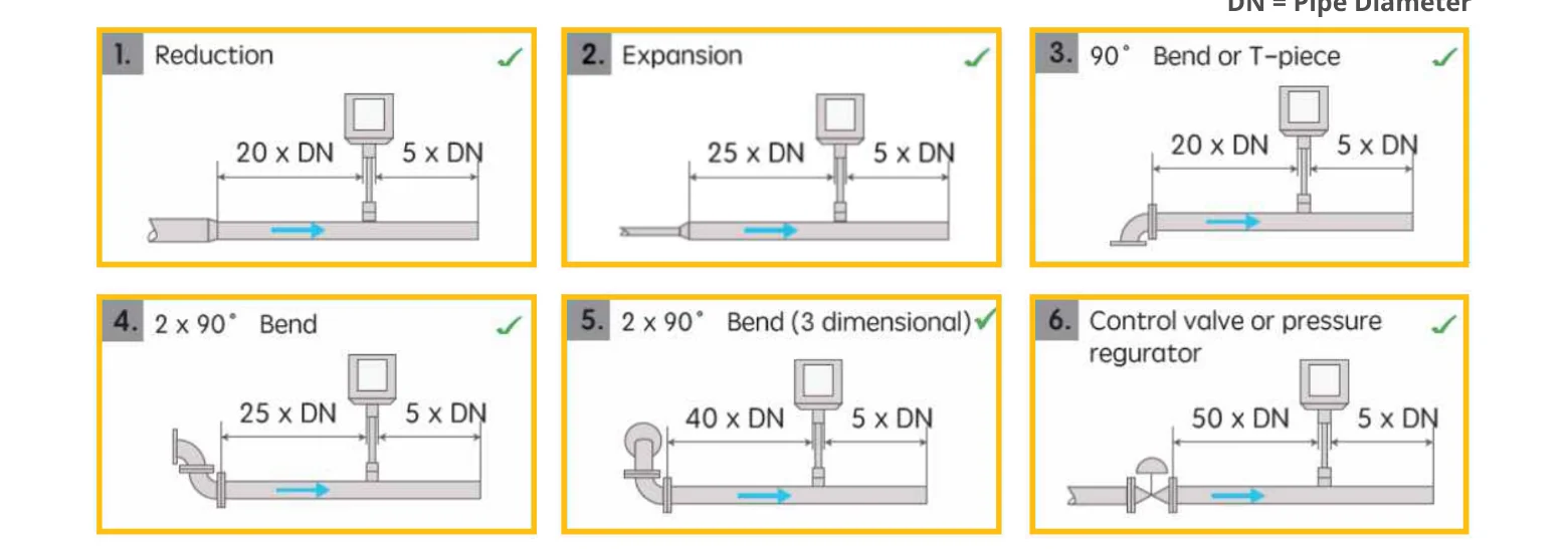
A thermal mass flow sensor needs a settled flow profile. Leave a straight pipe run of the lengths below upstream and 5 × DN downstream of the sensor (DN is the pipe diameter):
- After a reduction or a 90° bend / T-piece: 20 × DN upstream.
- After an expansion or two 90° bends in one plane: 25 × DN upstream.
- After two 90° bends in different planes: 40 × DN upstream.
- After a control valve or pressure regulator: 50 × DN upstream.
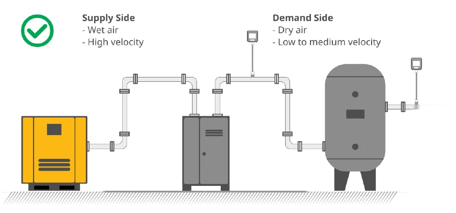
Install on the demand side, after the dryer, where the air is dry and the velocity is low to medium. Avoid the wet, high-velocity supply side between the compressor and the dryer.
The insertion type is installed online through a 1/2″ ball valve under pressure, so there is no downtime and almost no pressure drop. Above 1.6 MPa a high-pressure installation jig is required. If you are planning a full measuring point, our flow meter overview explains how to choose between insertion and in-line meters.
Ordering Code
WAFS 109 insertion type
| Code | Description |
|---|---|
| WAFS 109-A | Insertion type, 250 mm shaft (pipes up to 8″ OD), 0.1 … 250 Nm/s |
| WAFS 109-B | Insertion type, 400 mm shaft (pipes up to 24″ OD), 0.1 … 250 Nm/s |
| WAFS 109-C | Insertion type, 600 mm shaft (pipes up to 40″ OD), 0.1 … 250 Nm/s |
WAFS 109-IL in-line type (0.1 … 250 Nm/s)
| Code | Line size |
|---|---|
| WAFS 109-IL-A | DN15 (1/2″) |
| WAFS 109-IL-B | DN20 (3/4″) |
| WAFS 109-IL-C | DN25 (1″) |
| WAFS 109-IL-D | DN32 (1¼”) |
| WAFS 109-IL-E | DN40 (1½”) |
| WAFS 109-IL-F | DN50 (2″) |
Options
| Option | Insertion | In-line |
|---|---|---|
| Display: 2.0″ IPS LCD with capacitive touch panel | WAFS 109-L | WAFS 109-IL-L |
| Gas: nitrogen (N2) | WAFS 109-G02 | WAFS 109-IL-G02 |
| Gas: hydrogen (H2), real gas calibration | WAFS 109-G03 | WAFS 109-IL-G03 |
| Gas: helium (He), real gas calibration | WAFS 109-G07 | WAFS 109-IL-G07 |
| Gas: other specified gases | WAFS 109-G08 | WAFS 109-IL-G08 |
| High-accuracy calibration (1% of reading, ±0.3% FS) | WAFS 109-H | WAFS 109-IL-H |
| High pressure rating 0–40 bar | WAFS 109-PR40 | WAFS 109-IL-PR40 |
| High pressure rating 0–63 bar | WAFS 109-PR63 | WAFS 109-IL-PR63 |
| Wi-SUN sub-module, 915 MHz (Asia, America, Australia) | WAFS 109-WiSun915 | WAFS 109-IL-WiSun915 |
| Wi-SUN sub-module, 868 MHz (Europe, Middle East) | WAFS 109-WiSun868 | WAFS 109-IL-WiSun868 |
Model Selector (WAFS 109)
Use this selector to build the ordering code for your pipe and gas. Then send the code with your line pressure through the enquiry form below.
Need this for your plant?
Send us your line size, operating pressure and flow range and a WiseAir application engineer will confirm the right model, the delivery time and the price. We manufacture in India, so lead times are weeks rather than months.
Prefer to talk? Call +91 90477 78715 or +91 98944 49015. Not sure it is the right instrument? A compressed air audit tells you what to measure and where. Or start with our free compressed air calculators.
Related Products
More Flow Sensors
- WAFS 103 Pitot Tube Flow Sensor
- WAFS 103D Bi-Directional Flow Sensor
- WAFS 104 Thermal Mass Flow Sensor
- WAFS 105 Inline Flow Sensor
- WAFS 106 Thermal Mass Flow Sensor
- WAFS 107 Thermal Mass Flow Sensor
- WAFS 108 Compact Flow Sensor
- WAFS 1102 Vortex Flow Sensor
- Ultrasonic Flow Meter
- WUFS 905 Electromagnetic Flow Meter
Explore Other Solutions
WISEAIR TECHNOLOGIES INDIA LLP
# 12 Sri Venkatalakshmi Nagar, Singanallur,
Coimbatore – 641005 India.

WiseAir Technologies India LLP is part of the Systel Asia group — specialists in compressed air management and smart monitoring solutions across Asia since 2002.
© Copyright 2026. WiseAir Technologies India LLP
Need this for your plant?
Send us your line size, operating pressure and flow range and a WiseAir application engineer will confirm the right model, the delivery time and the price. We manufacture in India, so lead times are weeks rather than months.
Prefer to talk? Call +91 90477 78715 or +91 98944 49015. Not sure it is the right instrument? A compressed air audit tells you what to measure and where. Or start with our free compressed air calculators.
Related Products
More Flow Sensors
- WAFS 103 Pitot Tube Flow Sensor
- WAFS 103D Bi-Directional Flow Sensor
- WAFS 104 Thermal Mass Flow Sensor
- WAFS 105 Inline Flow Sensor
- WAFS 106 Thermal Mass Flow Sensor
- WAFS 107 Thermal Mass Flow Sensor
- WAFS 108 Compact Flow Sensor
- WAFS 1102 Vortex Flow Sensor
- Ultrasonic Flow Meter
- WUFS 905 Electromagnetic Flow Meter